

Terre Haute Cleanwater
The City of Terre Haute wastewater treatment plant , located along the Wabash River, east of SR 63 and south of Interstate 70 was originally constructed and put into operation in 1963 as a primary treatment facility. New facilities at that time included: pretreatment and primary treatment facilities, chlorination and digestion facilities, the administration/control building and the main lift station. In 1971, it was expanded to include secondary treatment with the addition of secondary clarifiers. Additional sludge handling and dewatering/storage facilities and fine-bubble diffusers were added in 1989. The two flow equalization basins were added in 1990 and the main lift station was upgraded with new screening in 1997.
Treatment Process Summary
The existing treatment facility contains several different processes which are summarized below. The existing NPDES Permit No. IN 0025607 indicates that the WWTP (prior to the upgrades currently being constructed) was rated for a design average daily flow of 24 MGD. The effluent discharge limits are based on a peak wet weather flow of 48 MGD.
All of these facilities are currently being renovated/expanded in Phase II of the facility's improvements project as described below. The preliminary treatment process consisting of the new headworks was completed in 2012 as Phase I of the project, also described below.
Main Lift Station
The Main Lift Station for the sewer system is located northwest of the intersection of Prairieton Road and Interstate 70, and consists of two buildings connected at an upper level. The first building houses the influent screening facilities. The original bar screens were designed to handle 60 Million Gallons Per Day (MGD). The improvement project of 1997 replaced the mechanically operated screens with similar type equipment and rated capacity. The second building houses the four raw sewage pumps and controls. The station was originally designed to pump 40 MGD with three vertical shaft pumps operating. In 1997, the pumps were changed to dry-pit submersible pumps and designed to pump 48 MGD to the wastewater treatment plant with three pumps operating. The force main to the plant is 48-inches in diameter. At the average daily flow of 12 MGD, the velocity in the force main is approximately 1.5 feet per second (fps). To prevent solids from settling out in the pipe, a velocity of 2-3 fps is required. The buildup of solids in the pipe can and has caused problems at the headworks of the plant when a surge of flow from a rain storm flushes the solids through the pipes. The buildup of the solids in the grit chamber lowers the holding capacity and sends more solids to the primary clarifiers to be removed when pumping sludge.
The wastewater treatment plant also receives wastewater from the following lift stations:
- Southside Lift Station (which has a self cleaning bar screen)
- Honey Creek Mall Lift Station
- The Federal Prison Lift Station
The current average dry weather flow from these three lift stations is estimated to be 1.5 MGD, with a peak of 5.0 MGD. Unlike the main lift station, these lift stations serve areas with separate sanitary sewers. There are sub-basins within those separate sewer areas however that have peak flows due primarily to inflow/infiltration during rain events that act similar to combined sewers. All flow from the four lift stations now discharges into the new Headworks facility constructed in Phase I of the treatment facility upgrades and placed into service in early 2012.
Preliminary Treatment
The original preliminary treatment processes, sometimes referred to as the headworks, was constructed in 1963. It consisted of 2 aerated grit tanks, 3 comminutors/grinders in channels downstream of the grit tanks and 4 pre-aeration tanks. The facilities were originally designed with a treatment capacity rating of 48 MGD. The grit was removed from the aerated grit tank with a clamshell bucket. The only improvement project to these facilities over the years replaced two comminutors with channel type grinders. Previous studies have indicated that the capacity for the preliminary treatment is limited to 40 MGD because of hydraulic problems with the comminutors/grinders (Terre Haute CSO Operational Plan - 2006). It has been estimated that these facilities only removed a small portion of the grit. The remaining grit passed through the facilities and degraded downstream equipment, created odors and made sludge handling more difficult.
These preliminary treatment facilities were part of the original construction and were up to date for the 1960's. The operational and maintenance difficulties and age of the units have made the preliminary treatment an inefficient process that affects the overall performance of the entire treatment facility. The upgrade of these facilities would significantly reduce problems in this area as well as the treatment performance and operational cost of the entire wastewater treatment plant.
The entire preliminary treatment process was replaced with the new Headworks facility constructed in 2011-12 and placed into operation in March 2012. The facility is describe in detail in WWTF Expansion Phase I (below)
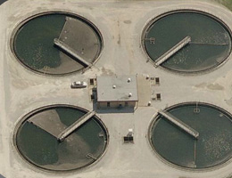
Primary Treatment
The primary clarifiers were part of the original 1963 construction. They were designed to treat wastewater flow of 48 MGD. There are four clarifier tanks with three channels per tank. The clarifiers’ longitudinal collectors act to move sludge to one end and cross collectors move sludge at the end of the channels to a common hopper for wasting. The effluent channel from the primary clarifiers was altered with a side channel weir in 1990 to discharge to the flow equalization (EQ) basins during high flow periods. This discharge to the EQ basins presently occurs at 24 MGD (the peak capacity of the secondary treatment process). The south end of the effluent channel has a sluice gate which is opened manually to act as a bypass when the EQ tanks are full and the flow rate exceeds the secondary treatment capacity.
Administration Control Building
The existing administration and control building was constructed in 1963. It is a two level brick building located near the entrance gate. The building contains various process equipment and control components, insufficient storage areas and personnel lockers in addition to the management and staff offices. It is undersized for current and future needs and approaching 40 years in age. The current location on the site is in a position relatively distant from most plant operational and maintenance activities. There is not sufficient parking. A properly programmed and designed facility to meet all the current and projected staff needs is desirable as the facility has served its useful life.
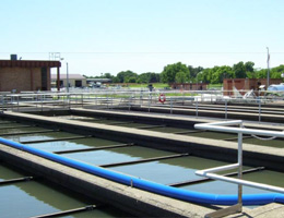
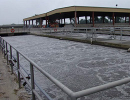
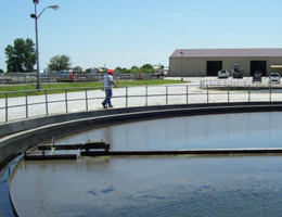
Secondary Treatment
The secondary treatment plant consists of aeration tanks and secondary clarifiers that were built in 1971. It is rated for 24 MGD. The four aeration tanks are comprised of three passes each and can be operated in step feed mode. There are four 100' diameter circular secondary clarifiers with 12' side water depth. The plant staff has operated these clarifiers up to the equivalent of 36 MGD during field testing and believes a higher rate is possible if flow splitting and piping improvements were available. Flow distribution between the aeration tanks and the clarifiers is not balanced. Better flow splitting facilities would help to balance out flows to all tanks and thereby increase performance and efficiency.
The discharge from the clarifiers is disinfected by utilizing gas chlorination and de-chlorination with sulphur dioxide. The wastewater is only disinfected during the recreation season (April- October) in accordance with the NPDES Permit. The disinfection system is sized for 48 MGD.
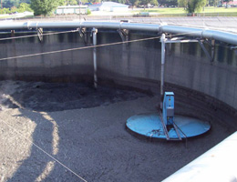
Bio-Solids
The original plant was constructed with anaerobic digesters and storage of liquid digested bio-solids in lagoons. In 1989, new belt presses and dewatered bio-solids storage facilities were constructed to allow disposal of liquid and/or dewatered bio-solids. Recently, the anaerobic digesters were converted to aerobic units with new diffusers and mixing systems. Most bio-solids processes and equipment with the exception of the digesters are in a deteriorated condition.
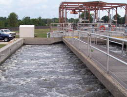
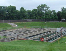
Flow Equalization Basins
The two earthen, lined flow equalization basins were constructed in 1990 and have a total volume of 5.2 Million gallons. The equalization basins receive primary effluent on flows greater than 24 MGD. Once the basins are full, approximately 24 MGD of flow continues to be sent to secondary treatment and the balance is bypassed from the primary effluent channel to the chlorine contact tank. When raw sewage flows subside, sewage from the basins can be pumped back into the pre-aeration tanks. The bypass weir in the primary clarifier effluent channel could be adjusted or replaced to increase the amount of flow sent to secondary treatment before discharge occurs to the basins.
WWTF Expansion - Phase I
Given the age and condition of the existing treatment facility, a preliminary engineering report (PER) was completed for the entire facility in 2008/09 during the latter stages of the CSO LTCP process. The PER recommended significant upgrades for the facility to address antiquated equipment and processes, operational issues, hydraulic/organic capacities, and to have the ability to meet future regulatory requirements. The improvements recommended were estimated at $130 million and were proposed to be completed in 2 phases over 5 – 6 years.
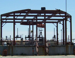
Phase I of the improvements to the treatment facility consisted of a new Headworks facility which initiated construction in late 2010 and was completed in early 2012. A summary of the new headworks facility is as follows:
The new headworks facility was constructed east of the existing aerobic digesters. New influent piping conveys all influent flows from the existing preliminary treatment structure to the new facility site. Two 24 MGD fine screens are followed by two 30 MGD Pista grit removal systems. The entire preliminary treatment facility is enclosed with ozone odor control equipment. Influent flow metering and sampling facilities are installed upstream of the influent screening. A flow division structure was initially installed downstream of the headworks structure to split flow to the primary tanks. The new headworks facility has a capacity of 48 MGD which will ultimately match the entire facility when all work is completed for Phase II.
WWTF Expansion - Phase II
The new Headworks at the wastewater treatment facility completed in 2012 was Phase I of the overall facility improvements. The remainder of the improvements to the facility, Phase II are currently under construction and scheduled to be completed by the end of 2015. Along with these improvements that will generally replace antiquated equipment, structures and processes, and increase the overall wet weather capacity of the plant to 48 MGD, it will also change the biological process to the Modified Ludzak-Ettinger Process. The various components of the treatment facility improvements project are generally described as follows:
- Demolition of Grit Tank and Pre-Aeration Tank
The existing grit chambers and pre-aeration tanks will be excavated and demolished after the new headworks is operational. - Anoxic Tank
Anoxic tanks will be constructed adjacent to the new aeration tanks which will receive the flow from the newly constructed headworks structure. There will be mixers installed within the anoxic tanks. These tanks are to be designed to hydraulically accommodate 48 MGD peak wet weather flow plus combined return activated sludge (RAS) and internal recycle flows for a total of 144 MGD through secondary treatment. The use of anoxic tanks will help control odors associated with the existing primary sedimentation tanks. - Internal Recycle Division Structure
Due to the high flow planned through the anoxic tanks, a new flow division structure downstream of the headworks is required. An internal recycle flow division structure will be built to accept the internal recycle flow from the aeration tank effluent (72-96 MGD), the RAS flow (24 MGD) from the secondary clarifiers and the influent flow (design 24 MGD, peak wet weather 48 MGD) and split the flow between the four (4) anoxic tanks. - Proposed Aeration Tanks
Four (4) new aeration tanks, an influent division structure, effluent division structure and piping are required to meet the higher flow demands. - Proposed Blower Building
A new blower building will be built to the south of the new aeration tanks to house six (6) 6000 scfm blowers to aerate all the aeration tanks plus two (2) 1000 scfm blowers to aerate the channels. - Existing Aeration Tank Upgrades
The existing four (4) aeration tanks will have upgrades which include concrete replacement of the top two (2) feet of all walls, increased wall height of two (2) feet, additional flow control weirs and replacement of the air piping, valves and diffusers. New influent and effluent flow splitting structures will be provided. - Existing Secondary Clarifier Upgrades
The existing rim flow secondary clarifiers will receive equipment replacement as well as minor concrete repairs. Influent and effluent piping will be replaced as needed. - Proposed Secondary Clarifier Tanks and RAS Pump Building
Two new secondary clarifiers will be constructed along with a new RAS pumping building, secondary effluent control box and piping. - Conversion to Ultraviolet Disinfection
The existing chlorine disinfection system will be converted to UV disinfection by modifying the chlorine contact tank and installing UV disinfection equipment. - Proposed Sludge Process Building
The gravity belt thickeners and belt filter press dewatering systems will be removed and replaced with rotary drum thickeners and centrifuges respectively. Four rotary drum thickeners (including one backup) and three centrifuges (including one backup) will be located in one building south of the dewatered sludge storage pad. The building will also include a 500,000-gallon waste activated sludge (WAS) receiving well, a thickened WAS receiving well and pumps.
The remaining sludge pad, approximately 166 ft by 60 ft, will run west to east and provide approximately 1330 cy of storage for the dewatered sludge from the centrifuges in the new sludge handling facility. - Proposed Liquid Storage Tanks and Odor Control/Pump Building
Four (4) 2.5 million gallon (MG) storage tanks will store either thickened WAS, aerobic sludge or both. The tanks will have wet scrubbers for odor control and jet mixing for aeration. - Waste Sludge Holding Tank Conversion
The primary tanks will be converted to four (4) waste sludge holding tanks — concrete will be repaired, primary sedimentation equipment removed. Once the demolition and repairs are made sludge screens and jet mixers installed to help with treatment of bio-solids. This will enhance the performance of the existing aerobic digesters. - Administration Building
A new administration building, which will also house a new laboratory and SCADA control center, will be located south of the southernmost entrance to the WWTP. The construction of the new administration building will help City alleviate American Disability Act (ADA) issues that are present at the existing administration building. - Plant Side Stream Lift Station
To accommodate upgrades to the WWTP including proposed sludge processes, a new lift station will be built to receive recycle water waste streams from throughout the WWTP and pump the streams back to the internal recycle diversion structure. - Proposed Internal Anoxic Recycle Pump Station
A pump station from the effluent division structure is necessary to pump the internal recycle flow to the internal recycle flow division structure upstream of the anoxic tanks. - Flow Equalization Basins and Odor Control System
The existing basins have liners that have pulled loose from the anchoring system and need replacement. The cleaning/wash down procedure for the basins will be improved with a connection to the new high pressure non-potable water system and a new water monitor system. - Electrical and Instrumentation and Control (IOC)
The electrical and I&C upgrades will be incorporated into the upgrades listed above and include replacing electrical equipment as needed, adding standby power for critical unit processes, and a new Supervisory Control and Data Acquisition (SCADA) system to provide supervisory control and monitoring from strategic remote locations.